| LARGEST NODAL DIFF | 0.0005 IN |
| TIME TO MATCH | 27 MIN |
| TIME TO APPLY TO CFD | 30 SEC |
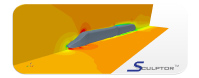
A turbine blade is a simple blade that is often combined with hundreds of other blades around a shaft or drum. Combined, these blades create a turbine which reacts in a jet engine with air thrust into the area around the blades. The air reacting with the turbine blade forces the shaft to rotate. In a jet engine this rotation assists the compressor blades that are crucial to compressing the air for the combustion of fuel.
There are a number of different processes that need matching, but a basic matching need arises when the designers want to create a computational fluid dynamics (CFD) model of a non-operating blade. The blades are modeled as operating or "Hot", using Finite Element analysis a "Cold" blade is created. The geometry of the cold blade then needs to be applied to the CFD model. There are a number of ways that this is done, but all are inefficient and costly, until now.
Sculptor™, enabled the customer to fit the two blades with appropriate tolerances, while minimizing the smallest difference. This was done by manipulating Sculptor's ASD volume while minimizing the sum of the differences of each node on the Hot and Cold FEA model. After the two FEA blades were matched, the deformation was applied to the volumetric CFD mesh and in a few moments the customer had a "Cold" CFD model. The entire blade matching process took less than an hour. The deformations were applied to the CAD model using Sculptor's Back2CAD module

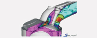
 The first step was to create the appropriate meshes and geometry. First the CAD model was created, next the CFD mesh was created, and finally an FEA mesh was created and analyzed. An ASD volume was created around the undeformed FEA mesh with groups that closely mimicked the deformations that the analysis made.
Sculptor™'s morphing technology was applied in conjunction with a script which was written to compare, node by node, the deformed and post-analysis meshes. Sculptor then made a deformation to the previously undeformed mesh and compared it to the post-analysis mesh.
 After the ASD deformation that provided the closest match was determined, the volume and deformation were applied to the original CFD mesh and the original CAD. A new CFD and CAD model were then exported and ready for a new analysis
Results Speeding up the optimization by using high-efficiency and parallel Optimizers such as modeFRONTIER's Evolution Strategies. When the optimal design has been obtained, re-creating the optimal CAD geometry is simple: the Sculptor deformation tool can deform the original CAD geometry in the same way as the mesh.

Sculptor™ is developed by Optimal Solutions Software LLC, based in Idaho, USA. The Optimal Solutions Management team is comprised of some of the most experienced CFD-based shape optimization personnel in the business. Since 1990, the re-search team has expended thousands of man-hours in design-ing and refining the Sculptor™ software program to its pre-sent form. Through the development of the Sculptor™ world-class, patent-pending product family, Optimal Solutions has been able to effectively address the current barriers that pre-vent the efficient use of digital simulation.
The team at Optimal Solutions Software is happy to perform a no-cost initial design assessment on your model. Contact Us today and we will obtain the deformation constraints from you and demonstrate how Sculptor can save you time and money. We have worked with all sizes of companies and have NDA's in place with most major firms and can quickly get to work on your model.
 Sculptor enabled optimization of the HVAC design resulting in significantly improved performance with an 89 % time savings and a 90% cost savings to the customer as compared to other methods.
 Sculptor enabled an 8% increase of overall lift/drag ratio, a 90 % time savings, and a 91% cost savings to the customer as compared to other methods.

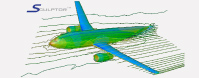
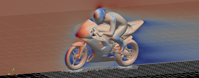
 Sculptor enabled optimization of the aerodynamic design with a 90 % time savings and as compared to other methods.
 Sculptor enabled the customer to match "hot" turbine blade models to "cold" shape with a 62 % time savings and a 62% cost savings to the customer when compared to other methods.

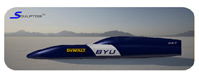
 Sculptor enabled optimization of the high speed train design resulting in reduced drag, reduced emissions and improved efficiencies with an 85 % time savings and a 92% cost savings to the customer as compared to other methods.

 Sculptor enabled evaluation of 124 design variants with an 86 % time savings and an 86% cost savings to the customer when compared to other methods.

 Sculptor enabled quick evaluation of multiple design alternatives resulting in reduced drag with a 79% cost savings to the customer as compared to other methods.

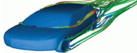
 Scultpor enabled finding the optimal vehicle aerodynamic design with 89 % time savings and an 81% cost savings to the customer when compared to other methods.